Debugging and De-bricking the Netgear R6200 via UART
Update: I forgot to credit my former colleague, Tim (@bjt2n3904), for helping me locate the UART header. This project would have been way more challenging without the serial connection. It would have involved desoldering the flash memory chip, probably replacing it with a ZIF socket, and then removing and reprogramming the chip for each iteration of testing.
In the previous installment, we filled out the ambit firmware header just enough to satisfy Netgear's broken UPnP server. We also patched out several
We're now at the point that emulation is no longer adequate; we need to start testing against actual hardware. There are subtle and not-so-subtle differences between emulation and hardware that affect how the exploit works. Some exploits, such as command injections and even buffer overflows, can be tested and developed entirely in emulation. Since this exploit writes a firmware image to flash memory, we need to ensure it is written to physical storage properly and will successfully boot and run.
In the previous installment, we filled out the ambit firmware header just enough to satisfy Netgear's broken UPnP server. We also patched out several
ioctl() calls in upnpd in order to test the SetFirmware exploit in emulation.We're now at the point that emulation is no longer adequate; we need to start testing against actual hardware. There are subtle and not-so-subtle differences between emulation and hardware that affect how the exploit works. Some exploits, such as command injections and even buffer overflows, can be tested and developed entirely in emulation. Since this exploit writes a firmware image to flash memory, we need to ensure it is written to physical storage properly and will successfully boot and run.
Experimentation with modifying a device's firmware calls for some sort of connectivity at a lower level than just a Linux shell. If the operating system fails to boot, there is no shell. We'll need to connect to the device in order to diagnose the problem and recover. The iterative process of developing the small, bootstrap firmware that I will describe later entails many incomplete builds that will leave the device in a semi-broken state. Knowing that you can recover by restoring a good firmware makes the project much less risky.
What you'll need for this part:
- USB to UART cable (described below)
- Soldering iron
- Torx screwdriver set (I like this one)
- Solid copper wire in a few colors (I think 22 gauge is fine here)
- 3 male-to-female jumper wires of different colors (black, orange, and yellow are ideal)
Hunting for UART Header
Fortunately the R6200 has a UART header you can connect to using a serial terminal application such as Minicom. With Minicom, you can interact with the bootloader to see diagnostic messages and even drop into a recovery console.
To interface with the R6200's UART, you can use a cable like the FTDI 3.3V USB to Serial cable, (part number TTL-232R-3V3-2MM). It's available from Allied Electronics, Amazon, SparkFun, and others.
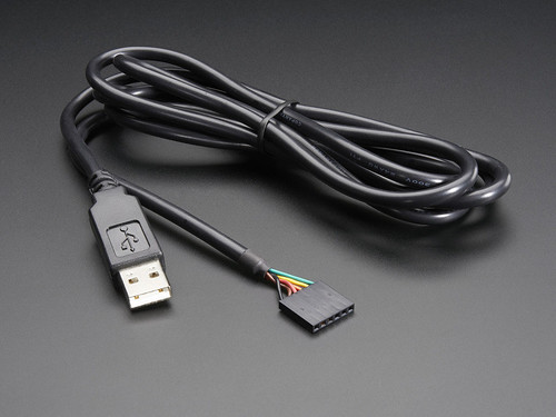 |
| USB to UART cable for serial debugging |
The UART connection isn't exactly set up and ready for you to use, though. This means taking apart your router and heating up your soldering iron.
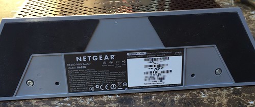
There are couple of torx screws that hold the base on.
There are couple of torx screws that hold the base on.
Then there are a couple more torx screws that hold the outer shell together. These are the same size as the previous ones, but different length. Keep them organized if you plan to put the router back together.
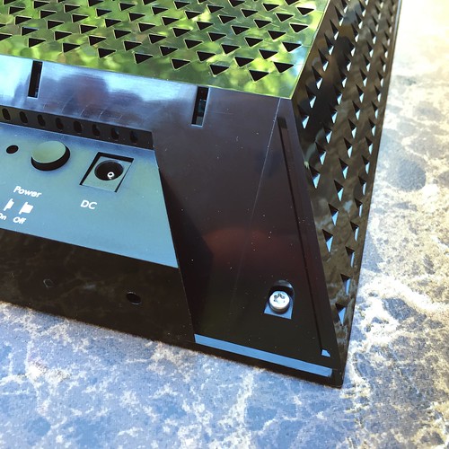 |
| More screws. |
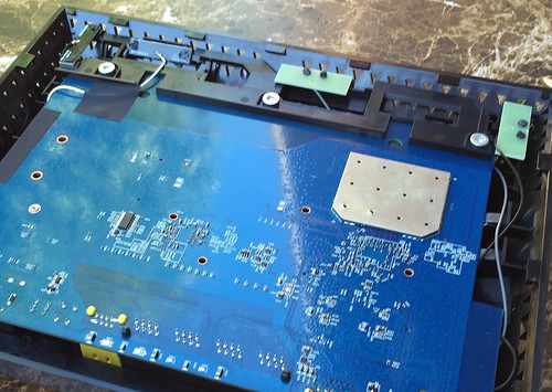
With the outer screws removed, you can start separating the front and back half of the clamshell. There are plastic tabs all the way around that hold it together. I broke a few trying to get it open. Once you get the front half off, you'll find the PCB held in by more torx screws.
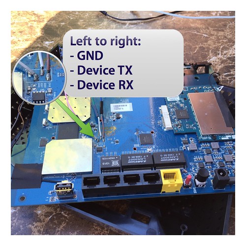
Once you remove the PCB, you can locate the UART header, which is exposed as four solder pads.
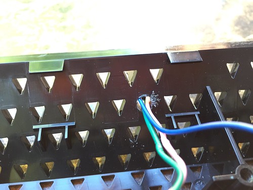
The solder pads, from left to right, are VCC, ground, transmit, and receive. You don't need VCC; it's +3.3V power. The USB adapter is powered by your computer's USB port, instead. That leaves ground, TX, and RX. The transmit and receive are relative to the device, so transmit from the device connects to receive of your cable and vice versa. Solder short leads to the appropriate pads, and connect your jumper wires to them. Then, route the jumpers out of the case so you can access the UART once you reassemble your router. I drilled a small hole in the top for a passthrough.
Here's how the UART header maps to the USB adapter's pinout:
- Device GND <-> Adapter GND (black)
- Device TX <-> Adapter RX (yellow)
- Device RX <-> Adapter TX (orange)
If you have orange, yellow, and black jumpers, connecting them up so the colors match the USB adapter will save you some trouble. Sadly, I had green, pink, and blue on hand, so mine is exciting and confusing every time I hook it up.
Then, I zip-tied the leads to reduce stress on them.
Connecting Using Minicom
You may want to test the serial connection before reassembling. The baud rate is 115,200 and serial port settings should be 8,N,1. Here's my mincom configuration for the R6200. Obviously adjust your ttyUSB device as appropriate, but it's usually/dev/ttyUSB0.######################################################################## # Minicom configuration file - use "minicom -s" to change parameters. pu port /dev/ttyUSB0 pu baudrate 115200 pu bits 8 pu parity N pu stopbits 1 pu rtscts No ########################################################################
When you connect with Minicom and power on the R6200, you can see the boot text scrolling across the console. If you let it boot, and hit return in the console, it gives you a root prompt. It's not a great terminal environment, though. There's no scrollback, for example. Once you have a serial console, use netgear-telnetenable[1] to fire up the telnet backdoor.
Shitty terminal environments aside, the serial console is great for restoring to a non-broken firmware. As long as nothing trashed the flash partition that contains the CFE boot loader, you can break in to a debug prompt and do a restore.
When you first power on the device and see CFE loading, break in with
ctrl+c. You need to break in right after CFE starts, but before it finishes loading the kernel and operating system from flash. Incidentally, this gets trickier after we shrink the firmware down from nearly 9MB to under 4MB because the load time shortens dramatically, narrowing the window when you can break in.Recovering a Bricked Router
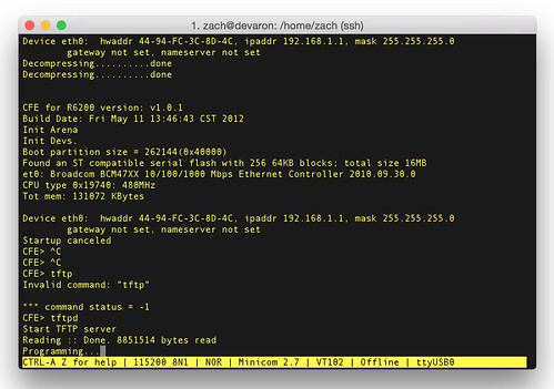
If you break in at just the right time (I just mashctrl+c repeatedly), you should get a CFE> prompt. Once you've got the prompt you can start up CFE's TFTP server with the tftpd command to restore a factory firmware. The router's network configuration is 192.168.1.1/24. There's no DHCP server in this mode, so you'll need to configure your own network interface manually. You'll need a tftp client to upload the firmware image. TIP: Be sure to switch your client to binary mode. This gets me every time.
When you reboot, the router should be back to normal. Now you can iteratively test custom firmware knowing that it only takes a minute or two to restore back to a good one.
In the next part, we'll regenerate the SquashFS filesystem. We'll also work on shrinking the firmware down to 4MB to avoid crashing
upnpd during exploitation. We'll need to hunt down and eliminate nonessential services, while avoiding breaking the boot sequence. Stay tuned!------------------------------
[1] Did you know that nearly every one of Netgear's consumer devices has a well-known but unacknowledged backdoor? It's true. What the fuck are we even doing here. Who needs trojaned firmware when Netgear devices already have a backdoor. http://wiki.openwrt.org/toh/netgear/telnet.console
